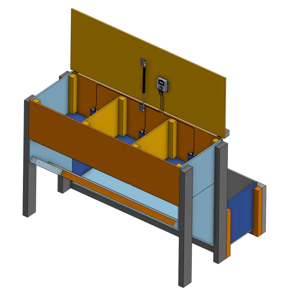
A horizontal hay cabinet is a practical and easy-to-use solution for automated hay feeding for horses. With all compartments at the same level, filling is easy and there’s no need to lift hay upward. Thanks to the gas spring, the lid stays open during filling without needing additional support.
With the HayTime Controller, horses receive hay from the hatches at precisely set times.
On this page you’ll find everything you need: two different models, complete drawings, and supplies with direct purchase links.
Choose a Model
The hay cabinet has three hatches and one HayTime Controller with three locks. Choose the model based on whether you want a hay trough underneath the cabinet or not.
Basic Model (Horizontal 3)
A simple model without a hay trough. Suitable when hay can fall directly to the ground.
📐 Download Drawings – Basic Model (PDF)
Model with Hay Trough (Horizontal 3 with trough)
The cabinet has a fixed trough where hay falls from the hatches. Keeps hay neatly in one place, prevents hay from contacting ground material, and reduces waste. See the accompanying image.
📐 Download Drawings – Model with Hay Trough (PDF)
Also see the 3D model of the hay cabinet.
What You Need
You can order the HayTime Controller from the haytime.fi online store. The package includes:
- HayTime Controller
- Your chosen number (1-3) of locks
- Cables with desired length selected on the product page
You can obtain lumber and metal parts, for example, through the links below. Required screws: 4×50 mm (200 pcs) and 3×12 mm (100 pcs) – these are available from the same stores.
Note: Always pre-drill holes through the plywood before screwing. Maximum screw length at hinge points is 12 mm, elsewhere 55 mm.
| Supply | Without trough | With trough | View item |
|---|---|---|---|
| Lid hinges – Arctic Marine 129×40 mm, AISI316 | 2 | 2 | View |
| Hatch hinges – Pisla 50×40 mm (2 pcs/pkg) | 3 pkg | 3 pkg | View |
| Screw 4.2×45 mm stainless (250 pcs/pkg) | 1 pkg | 1 pkg | View |
| Screw 3.5×12 mm countersunk, galvanized | 1 pkg | 1 pkg | View |
| Gas spring 400 N / 150 mm | 1 | 1 | View |
| M8 serrated flange nut (12 pcs/pkg) | 1 pkg | 1 pkg | View |
| Corner bracket for gas spring 50×50×35 mm | 2 | 2 | View |
| Film-faced plywood 1250×2500 mm, T=12 mm | 3 | 2 | View |
| Pressure-treated timber 48×48 mm, 4.2 m | 4 | 2 | View |
| Pressure-treated timber 48×98 mm, 3.6 m | 2 | – | View |
| Pressure-treated timber 48×98 mm, 4.2 m | – | 1 | View |
* No reference link available for corner brackets – check a suitable model at your local hardware store. Screws: 4×50 mm (200 pcs) and 3×12 mm (100 pcs) are available at the same stores.
Building Steps
Detailed measurements and images can be found in the PDF drawings. Below is a rough step-by-step guide to support construction.
Step 1 – Base Structure
Assemble the base from eight 48×48 mm battens (L=330 mm) and two plywood sheets (1470×350 mm, T=12 mm). The battens form a platform that keeps the cabinet off the ground.
Step 2 – Partition Walls
Attach partition walls (2× plywood 500×350 mm and 2× plywood 500×335 mm) so that there is clearance for control cables. Check cable opening locations from the drawing before attachment.
Step 3 – Side Walls
Assemble side walls from two 524×566 mm plywood sheets and four 98×48 mm battens (L=1050 mm). The battens serve as support framing for the side walls.
Step 4 – Hatches
Attach three hatches (500×465 mm, T=12 mm) with hinges. Use screws no longer than 12 mm at hinges. Hinge locations can be found in the detail view of the drawing.
Step 5 – Lid and Frame
Assemble the lid frame from two 48×48 mm battens (L=650 mm) and one batten (48×48 mm, L=1340 mm). Attach plywood cover (1438×450 mm, T=12 mm). You can adjust this measurement to fit your cabinet if needed.
Step 6–8 – Gas Spring and Lid
Install the gas spring using angle brackets so that it supports the lid open during filling. Check gas spring installation details from the drawing – the correct mounting angle is important for functionality.
Step 9–10 – HayTime Controller Installation
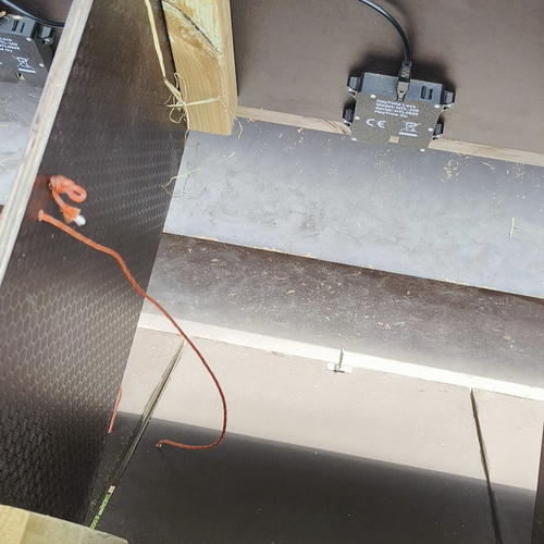
Attach the HayTime controller to the bracket in the cabinet. Connect cables to the three locks (2× 1 m cable, 1× 0.5 m cable). The controller is programmed in the HayTime app – download the app and follow the setup instructions.
Model with Hay Trough: Additional Steps (steps 11–14)
Build the trough from additional parts: two plywood sheets (1470×400 mm and 1470×430 mm), two end panels (418×400 mm), and support beams. The trough is attached to the front of the cabinet so that hay falling from the hatches is directed into it.
Did You Build the Cabinet?
We want to see it! Tag @HayTime on Facebook or @haytime.fi on Instagram
Drawings: HayTime Oy / Marko Ridal. Prices and availability of supplies must be verified from the online store.
Watch the video below to see how a self-built hay cabinet works. The video shows a six-portion cabinet.